UKTA is the Professional Association for thermographers in the UK and the rest of the world with the common goal of furthering all aspects of thermography.
This is our old website. Please go to the new one at www.ukta.org ----------
ISO starts on thermographic standards
The International Standards Organisation Technical Committee, TC135 has approved a new work item on Thermographic Standards. TC 135 develops standards for non-destructive testing and the sub-committee SC8 aims to develop standards for thermographic terminology, methods, and equipment. The work item was proposed by the American Standards organisatuion, ANSI. UKTA will be closely involved to ensure that thermographers and thermography users in the UK are not disadvantaged.
Newcastle Conference
The UKTA session at the BINDT annual conference in September proved popular, with nearly 40 delegates opting to hear about thermography rather than other NDT methods. The session opened with Geoff Holah reviewing NDT applications for thermography including some of the less well known. He talked about corrosion detection under insulation or in cement lined pipelines, delamination and faults in cathodic protection of concrete, buildup of sediment and refractory loss.
Ian Munns of TWI talked about the use of thermography in the study of welds and the welding process. The ability to view welds rapidly and without contact gives thermography a distinct advantage over other methods.
The next paper described a method under development to detect insulation faults in aircraft wiring looms. It uses a dielectric spray to induce heating by leaking current which can then be detected by thermographic inspection.
Finally Bob Howes showed his professional approach to winning clients for his thermographic services with examples of his work and high quality presentation graphics.
Spring Conference Committee please!
UKTA will run a one day conference in Spring 1999. The proposed format will allow four papers on thermographic applications, a session on the needs of the industry and the UKTA AGM. If you wish to speak at this conference please contact the secretary now.
Organising a conference of this type takes a considerable amount of work and cannot be achieved without a dedicated conference committee. With a committee of four or five people each member will only have to put in a few hours a month to organise, speakers, publicity, venue and bookings. Please join this committee and help to make this the best Thermography conference in the UK.
International Conferences
IR/INFO ’99
January 17-20, 1999, in Las Vegas, Nevada expect to hear success stories, proven techniques, and interesting case histories. Learn more about program and cost justification, results of technological research, and equipment updates.
Thermosense XXI
April 5-9, 1999 in Orlando, Florida. Every year this infrared conference, sponsored by SPIE, draws professional thermographers from around the world with papers in the following areas:
•Buildings and Infrastructure
•Predictive Maintenance
•Process and Product Monitoring
•Nondestructive Evaluation
•Research and Development Applications
ITA 1999
May 9-11 1999 in Phoenix Arizona. International Thermography Association meetings attract around 70-100 thermographers from at least eleven nations to some of the most lively thermographic presentations.
Online Application Library
ITA are producing an online application library to be accessed through the internet. They are asking for contributions to help build this into a useful resource.
Industry News
Management of IR predictive maintenance
Inframetrics have brought automated report generation a step closer with their new Condition RED® software and barcode labelling. The software package integrates the IR camera and IR analysis package keeping track of the plant equipment inventory in an easy-to-operate database.
The package reduces time analysing images, extracting temperature values and keying-in equipment identification information. A complete report of every inspected machine or system, together with a summary page outlining problem components, can be generated without additional user input.
Analysis Wizards allow users to specify criteria to analyse and categorise the problems identified in the images, automatically. Customised reports are generated automatically in Microsoft Word™.
To provide full relational database capabilities it utilises the Microsoft JET™ database engine. Each item for inspection is documented with detailed information about the equipment together with a visual reference or thermal image for ease of identification. The database, also allows the user to integrate and share information with other open architecture databases and other types of inspection equipment by using its DataBoard™ technology.
Process Automation
FLIR Systems - Automation Group are promoting a remote version of their ThermoVision® imager for process monitoring and automation. This complements their popular ThermoProfile® line scanner and allows them to offer a comprehensive package that will integrate with most process control systems.
FLIR systems have also released new versions of their reporting software IRWin 5.3 and report viewer 5.31.
Member Profiles
We print profiles of members in each newsletter so you get to know them.
Phil Kolbe, British Institute of Non- Destructive Testing, UKTA Committee member
Phil Kolbe is Technical Secretary and Deputy Secretary of The British Institute of Non- Destructive Testing. He gained an Honours Physics Degree at the University of Manchester in 1979 and subsequently joined British Steel, working in the NDT Research Department of the British Steel Technical Department, based at Corby in Northamptonshire.
Phil soon realised that by nature he was more of an engineer than a physicist and after a couple of years transferred to NDT Applications where the objective was to design, build and install automated tube testing systems. In 1989 Phil was promoted to a managerial position handling all contract work undertaken by the Technical Centre covering disciplines as diverse as Chemistry, Metallurgy, Welding, Welder Approval, Electronics and NDT. Phil retained responsibility for NDT Special Projects.
With re-location of the Technical Centre in 1990 Phil and his family opted for voluntary redundancy rather than re-location and as one door closed another opened. He joined The British Institute of Non-Destructive Testing as Technical Secretary. Although removed from the practicalities of NDT the job is interesting with Conferences to organise, Committees to look after, technical enquiries to answer, in short anything and everything that is to do with the well being of the Institute Members. The Institute has a special interest Condition Monitoring Group which encompasses Thermography hence the dialogue with UKTA.
Phil's position as an Ordinary Member working alongside the UKTA Executive Committee is unique and was devised to forge a strong link between UKTA and BINDT. The plan is working well with several joint ventures and on all issues to date there has been honest and lively discussion, exploring issues from several different viewpoints which must be of benefit to all concerned.
Telephone: 01604 630124 Fax: 01 604 231489 Telex: 31612 OTSSG
Andrew Nowicki, InfrRed Inspection Services
Andrew obtained a Higher national Diploma in Mechanical Engineering in 1959. His first employment was with the Production Research Association specialising in machine tool vibration. During the next ten years he worked in various capacities in what became a TI Machine Tool Division as a Development Engineer on machine tool and electrical, hydraulic and pneumatic control systems, eventually becoming Chief Engineer and gaining Membership of the Institution of Mechanical Engineers. He then spent five years as Technical Director at Samual Pegg, a company specialising in development and manufacture of textile dying machines. In 1979 he started IRIS, Infrared Inspection Services, initially concentrating on surveys of electrical plant but subsequently covering all aspects of thermography on a consultancy basis.
Newsletter topics
UKTA news is normally published in January, April, July and October. We apologise for the late arrival of this issue. Deadlines for information to go into a newsletter are the last day of the preceding month, however it is 8th January for the January 1999 issue. Topics will include news of:
· Profiles of members
· Members activities
· New Standards
· Courses / Meetings
· Exhibitions
· Case studies
· Industry developments
Case Study
THERMOGRAPHIC SURVEY OF STEAM TRAPS
from Andrew Nowicki
It is said that thermography can be successfully used to detect defective steam traps and for the most part this statement is correct, however, there are a number of pitfalls that the Thermographer must be aware of so as not to draw incorrect conclusions.
In a correctly designed system the steam trap will be placed at a point where most condensate is likely to collect and, therefore, the steam trap is likely to pass condensate at frequent intervals and under these conditions the temperature of the exhaust pipe in a closed system is likely to be reasonably steady, i.e., no cyclic effect is likely to be seen.
Float traps normally discharge condensate at steam temperature.
Inverted Bucket traps at medium or heavy loads discharge condensate intermittently but at light loads tend to dribble the discharge.
Thermostatic traps normally discharge condensate below the saturation temperature and in theory it should be possible to detect a leaking trap by measuring the rise in temperature of the condensate line, which should be close to the saturation point temperature, however, in practice it will be very difficult to obtain accurate temperature readings.
Thermodynamic traps, some discharge condensate close to steam pressure and others discharge below saturation point.
Before undertaking this type of work the Thermographer should be aware of the basic steam theory. Steam pressure and temperature are related and the data can be readily obtained from steam tables. The tables also show that the temperature of the condensate discharged from the steam trap will depend on the back pressure in the condensate return system and this is the first pitfall to overcome since in most cases it is impossible to establish the back pressure just behind the steam trap; in most instances there would be no pressure gauge fitted at these points.
As an example let's consider a float trap operating under the following conditions:
Operating pressure: 10 bar
Condensate return pressure 0.7 bar
Upstream of the trap the steam will be at a saturation temperature of 184°C, corresponding to 10 bar and immediately downstream of the trap the condensate temperature will be 115°C, corresponding to 0.7 bar. As condensate is discharged some flash steam will also be produced due to the sudden drop in pressure across the steam trap. The temperature of 115°C will hold good even if some live steam is also discharged with condensate by the trap into the drain pipe. All that happens is that the steam will give up its heat to re-evaporate some of the condensate in the return line, reducing the temperature from 184°C towards 115°C. This drop in temperature and associated re-evaporation of Condensate occurs so rapidly that the condensate line rise in temperature will only be marginally above 115°C and the actual rise may be impossible to measure with a handheld infrared system due to the measuring errors contributed by all the unknown factors listed.
In addition to the condensate back pressure, the Thermographer needs also to know the emissivity of the condensate return pipe and the effect of any external cooling, such as wind; in most instances all three are unknown.
Table 1 pressures and corresponding condensate temperatures
|
0.95bar |
98°C |
0.6 bar |
114°C |
|
0 bar |
100°C |
0.8 bar |
117°C |
|
0.2 bar |
105°C |
1.0 bar |
120°C |
|
0.4 bar |
110°C |
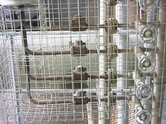
The thermogram shown in fig.1, on which are also shown condensate line temperatures at various emissivities, illustrates clearly the dilemma facing a Thermographer. As can be seen, thermography is an excellent tool for detecting non functioning steam traps, where trap 3 is cold, indicating that the system is either switched off or the trap is blocked. The problem is what to make of traps 1, 2 & 4.
Figure 1, Four steam traps as seen and a thermogram
Table 2 Temperatures of areas in figure 1
|
Area |
Temp, °C |
Rise, K |
|
01 |
131.9 |
31.9 |
|
02 |
98.5 |
-1.5 |
|
03 |
132.2 |
32.2 |
|
04 |
100.3 |
0.3 |
|
05 |
118.5 |
18.5 |
|
06 |
99.7 |
-0.3 |
If there is no back pressure and the emissivity is 0.90 then trap 1 & 4 are good and trap 2 may be slightly suspect.
If there is no back pressure and the emissivity is above 0.8 then all three traps are suspect.
If the condensate back pressure is above 0.7 bar then all three traps are functioning correctly.
Fig.2 shows a thermostatic steam trap discharging condensate through a pipe to atmosphere and close to it is an identical pipe discharging live steam to atmosphere and, as can be seen,
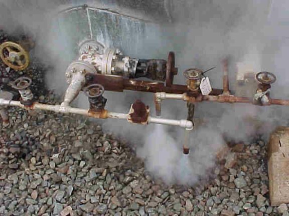

Figure 2, Two steam traps
the difference between the temperature of the two pipes is less than 10K, which under normal closed circuit operating conditions will be difficult to detect since this temperature rise is well within the possible measuring error band.
Fig.3 shows a thermodynamic steam trap discharging condensate to atmosphere and, as can be seen from the two thermograms, the difference in temperature between the trap idling and passing condensate can clearly be seen, however, were the trap discharging into to a closed circuit system the situation may be different. In most instances condensate will be trapped in the return pipe and its temperature will be close to that of the discharge from the trap. If any live steam passes through the trap it will cause the condensate to flash off into steam and the temperature of the condensate return pipe will always stay close to the discharged condensate temperature.
So Thermographers, especially those working as Consultants, take your pick what conclusions to draw from a thermographic survey of steam traps and ultimately what to tell our clients?

Figure 3, Two images of the same steam trap
Position sought
Bob Macgowan, currently working in New Orleans, Louisiana, is looking for employment in Scotland from May of 1999. He has 9 years experience as a Certified thermographer Level II #128 from the Academy of Infrared Thermography. He has previously worked for companies throughout the USA with Inframetrics and Agema equipment on all applications of thermography. He also has experience in the US Army and lists his hobbies as Photography, Computers, Skydiving and Creative Writing.
Web Sites
The UKTA web site has moved. It can now be found at https://members.tripod.com/ukta
This site includes over a hundred links to other thermography sites on the web.
Snell Infrared have a useful glossary of terms used in thermography at:
http://www.snellinfrared.com/resources/glossary.html
Meetings
Members' meetings are being planned for 10the March and
26th May Please keep these dates free. Topics include:
· Infrared company visit
· Meteorology and remote sensing Met. Office or ECMWF
· Marine Engineering / Royal Navy
· Electrical Power Industry / Nuclear Electric
c/o BSRIA Old Bracknell Lane West, Bracknell, Berkshire, RG12 7AH
Officers: Chairman - Dave Dibley, Vice Chairman - Dave Cannon, Treasurer - Peter Pollard, Secretary - Colin Pearson,